News
Factors Causing Instability of the Detection System of Infrared Carbon & Sulfur Analyzer
Introduction
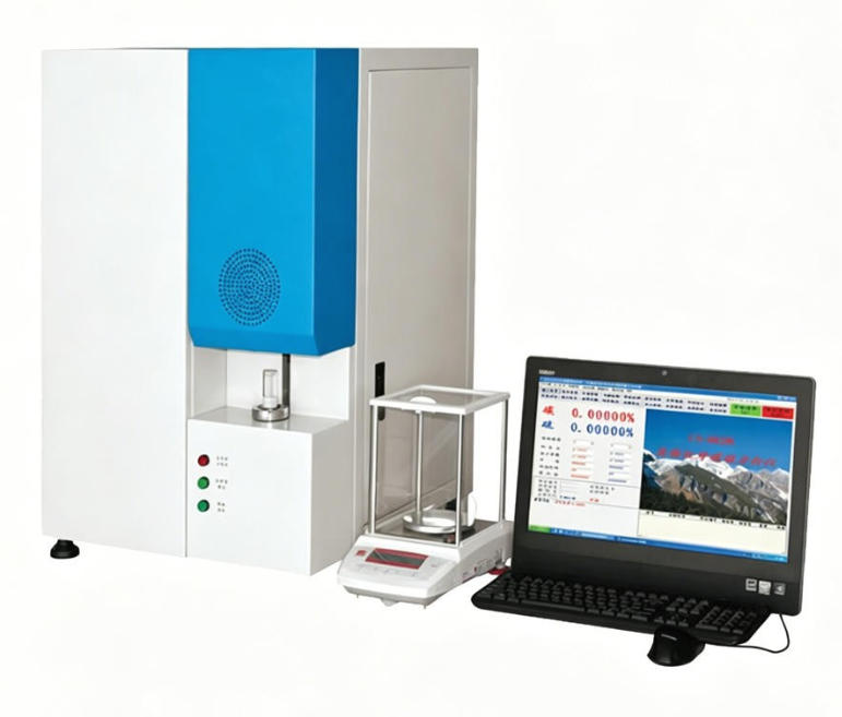
The infrared carbon & sulfur analyzer is one of the essential analytical instruments in metallurgical and machinery industries. It can rapidly quantify carbon and sulfur content in solid materials including steel, iron, copper, alloys, carbon compounds, ores, cement, ceramics and glass.
The detection system serves as the core of the carbon-sulfur analyzer. Maintaining a stable baseline output of the detection system is critical, yet numerous factors can trigger system instability, which imposes high technical requirements on operators and maintenance staff. Analyzing these destabilizing factors is of great significance for equipment maintenance and uninterrupted scientific research and production. For many years, unstable detection performance has been a common headache for instrument users. Through long-term research and maintenance practice, we have accumulated rich experience troubleshooting this equipment, which helps improve equipment utilization, guarantee smooth R&D and production tasks, and lay a solid foundation for routine maintenance of infrared carbon & sulfur analyzers.
2 Working Principle of the Instrument
Samples are delivered into a high-frequency combustion furnace and fully oxidized by oxygen at high temperature, converting carbon and sulfur in the specimen into CO₂, CO and SO₂.
The oxidized mixed gas passes through a dust removal unit and moisture purification device, then is carried by oxygen into the sulfur detection cell for sulfur measurement. The gas mixture containing CO₂, CO, SO₂ and O₂ flows into a heating catalytic furnace, where catalytic conversion takes place: CO → CO₂ and SO₂ → SO₃.
After passing through a sulfur absorption reagent tube, the treated gas enters the carbon detection cell for carbon measurement. Residual gas is exhausted outdoors from the analyzer.
Output signals from carbon and sulfur detectors are amplified by preamplifiers, converted via A/D modules, and transmitted to the microcomputer system for data processing to calculate the mass percentage of carbon and sulfur in the sample.
3 Analysis of Factors Causing System Instability
The measured signal of the specimen is closely related to the power supply output of the detection system, infrared source radiation power, chopper motor frequency, infrared photodetector, A/D converter, as well as external interference sources. Detailed root causes are sorted as follows:
3.1 Working Power Supply
The detection system operates on multiple power rails: ±15 V, 5.5 V, 24 V and 5 V, which are prerequisites for normal system operation. Abnormal circuit performance and output voltage arise from two main issues:
- Aging of electronic components leads to unstable output voltage and excessive ripple. The allowable fluctuation range of power supply output is ±10%; any deviation beyond this threshold indicates a fault.
- Damaged components result in zero output or distorted output waveforms. Faulty elements can be located by measuring voltages at key circuit nodes and comparing readings with standard values.
3.2 Infrared Light Source
Infrared radiation emitted by the light source is proportional to its optical power. Variations in radiant power directly change signal output amplitude, which shifts the detector baseline — any fluctuation in infrared radiant intensity will be reflected on the baseline reading.
Three typical root causes for unstable radiation signals:
- Gradual aging of the light source reduces radiant intensity and lowers signal output. Baseline readings of carbon and sulfur detectors will drop continuously, triggering instrument alarms once values fall below the normal range.
- Broken or desoldered heating wire of the light source causes complete loss of output signal. Check if the resistance of the heating wire matches the standard value (normally around 5 Ω).
- Cold solder joints or oxidized power plugs create poor contact. Variable contact resistance leads to violent, erratic fluctuations in signal output, a fault frequently overlooked by operators.
3.3 Chopper Motor
The chopper motor modulates continuous infrared light into periodic pulsed signals for the detector, a design that ensures stable amplified signals after circuit processing. Malfunction of the motor leads to weak or zero detector output, with three common failure modes:
- The motor fails to rotate, caused either by power supply faults or mechanical jamming of the chopper blade.
- Long-term operation causes severe wear of the motor shaft sleeve, increasing internal clearance. The chopper blade rotates unsteadily and may collide with the inner wall of the detection cell, resulting in mechanical blockage.
- Deviation of the motor modulation frequency from the standard value leads to inconsistent light transmission through the aperture, causing fluctuating or zero signal reception at the detector.
3.4 Infrared Detector
The infrared detector is a core gas analysis component that converts optical infrared radiation into electrical signals. Stable ambient temperature must be maintained during operation to avoid interference noise. Common faults include:
- Complete component failure with no signal output.
- Component aging reduces sensitivity and introduces heavy signal noise.
- Oxidized or cold solder joints cause intermittent poor contact, leading to unstable output signals.
3.5 Preamplifier
The preamplifier amplifies weak detector signals, filters interference and provides DC amplification. Minor defects in any sub-module will distort amplifier performance:
- Degraded micro-signal amplifier performance. Focus inspection on filter capacitors and grounding integrity during troubleshooting.
- Poor contact of zero-adjustment and gain potentiometers. Rotate the potentiometers back and forth several times during maintenance to restore good contact.
- Reduced gain of the quad operational amplifier results in low final analysis readings.
3.6 A/D Conversion Board
Voltage signals are sampled by a 16-channel chip, converted into digital signals via the A/D chip, and sent to the computer for calculation. Interference during this conversion distorts real-time monitoring, integral measurement and data computation. Key triggers:
- Aging and performance degradation of A/D board components increase interference noise and garble digital signals.
- Poor instrument grounding introduces external electromagnetic interference, causing missing sampled data.
- Loose contact between the A/D conversion board and the bus slot leads to loss of measured data.
4 Conclusion
Analysis of these destabilizing factors provides effective solutions for common malfunctions including unstable/zero signal output, excessive voltage ripple, heavy signal noise, missing or lost sampled data caused by aging and performance degradation of electronic components. This research greatly improves equipment utilization efficiency.
RELATED NEWS
NEWS CATEGORIES
LATEST NEWS
- Differences of Cantilever‑Beam and …
- Mooney Viscometer: Quality Indicato…
- Factors Causing Instability of the …
- Functions of Carbon & Sulfur Analyz…
- In-depth Analysis of Gas Chromatogr…
- Application of contact angle tester…
- Test Method for Sealing Performanc…
- Bottle Cap Torque Tester…
- Hardness testing of metallic materi…
- Applications of melt flow indexer…
- Introduction of new Hydraulic Flat…
- Guide to Maintenance of Drainage Sy…
- Constant Temperature and Humidity C…
- Common Faults and Solutions for COD…
- Tape peeling test of tensile testin…
- Understanding the sampling frequenc…
- Application of melt flow indexer (…
- Revolutionizing Precision: Digital …
- Application Solution for Oil and Fa…
- A Critical Tool for Ensuring Mater…
Contact
CONTACT USName: Jennifer
Mobile:+86 13336040868
Tel:+86 13336040868
Whatsapp:+86 13336040868
Email:sales@iqctest.com
Add:No.51 of Xiba Road,Wuchang Street, Yuhang District, 311100 ,Hangzhou City, China